

9 Diagrams view
Create telecom service diagrams.
The centre of this area is occupied by the workspaces in which telecom service diagrams are drawn. Below this area is a row of tabs, to create an additional service and to switch between services. Above this area you find buttons to activate the Library and Options panels, a row of templates, and the name of the active project.
9.1 Templates
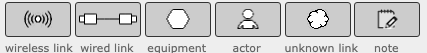
Templates contain default settings for new diagram nodes. You create new nodes by dragging one of the templates into the workspace.
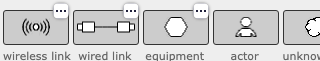
For the first three elements (wireless links, wired links, and equipment items), you can modify the predefined checklists. Click the edit indicator (the box with three dots) to open the checklist window for that element type.
9.2 Checklist windows

Wireless links, wired links, and equipment items each have a list of common vulnerabilities. These vulnerabilities apply to all nodes of that type. In the checklist window you can:
- modify the name or description of a vulnerability by clicking that item (press Enter/click elsewhere to confirm, press Escape to cancel)
- modify the type between natural and malicious using the icons on the left.
- remove a vulnerability, by clicking the minus-button on the right.
- add a new vulnerability, by clicking the “+ Add vulnerability” button.
- reorder the vulnerabilities, by dragging them into the desired order.
Any changes you make will affect all current and future nodes as well.
9.3 Service tabs
The workspace is the areas where the diagrams for telecommunication services are drawn. A project consists of one or more services. For each service, you can draw a telecom service diagram, and perform vulnerability assessments on nodes.
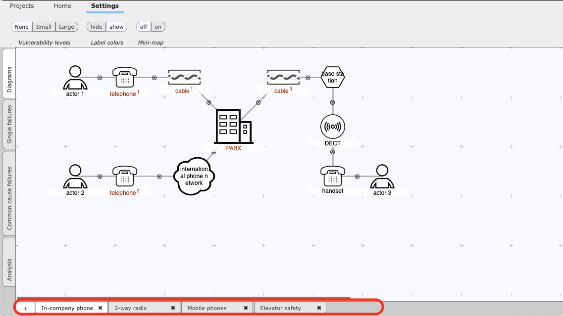
Each service has a tab at the bottom of the screen. You can:
- remove a service, by clicking the close (“cross”) button on its tab. Note that you cannot remove the last service of a project. If you try to, the workspace will flash briefly.
- add a new service to the active project, by using the plus-button.
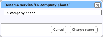
- rename a service, by double-clicking its name. The popup window shown below allows you to enter the new name.
- re-order the services, by dragging the tabs into the desired order.
9.4 The mini-map
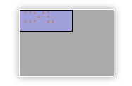
The workspace onto which nodes are drawn and connected, is larger than can be displayed on the screen. Use the mini-map to change the current view. The large grey area of the mini-map represents the total available workspace, while the smaller blue rectangle corresponds to the area that is currently visible (the workspace). Each red dot is one of the nodes in the diagram. Each red dot outside the blue rectangle indicates a node that is currently not visible.
Drag the visible area, by dragging the blue rectangle around. Or move the mini-map itself when it gets in the way, by dragging the grey rectangle around. You can also switch the mini-map off on the Settings toolbar.
When your diagram gets large, you can use the Zoom In, Zoom Out functions of your browser to fit more of the diagram onto the screen. The View-menu of the standalone tool also contains a Zoom function.
9.5 Diagram nodes
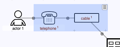
You create new diagram nodes by dragging them from the templates at the top of the screen. Each node is visually represented as a shape with its name inside or below, and up to five decorations that will become visible when you approach the node with the mouse.. Clockwise, starting from the top left corner:
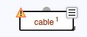
- The warning triangle in the top-left corner indicates that the node has too few or too many connections. View the warning report, by clicking on the warning triangle.
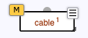
- The vulnerability level indicator in the top-left corner indicates the overall risk level for that node, using a colour. You can change the size of the vulnerability level indicator.
- The round connector at the top middle is used to link nodes together.
- The drop-down indicator in the top-right invokes a menu with actions.
- The resize indicator in the bottom-right allows the size of the node to be adjusted.
Move the node to another location on the workspace by dragging it around.
There are two ways to move more than one node at the same time. Hold the shift key while dragging a node to move all nodes in the diagram. Alternatively, create a selection, and drag the selection rectangle to move the selected nodes only.
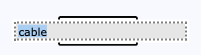
Rename a node by clicking its title. Note that the area becomes blue when you hover the pointer over the title. Confirm by clicking somewhere outside the workspace, or press Enter. Cancel the action (that is, revert to the current title) by pressing Escape.
9.6 Node classes
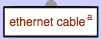
Nodes that are very similar can be made into a node class. Node classes are marked by a dark red colour. All nodes of a class share a single assessment of vulnerabilities. To be able to distinguish individual nodes in a class, each node is automatically assigned a letter, shown to the right of the name. This letter can be changed to something more meaningful using the “Change suffix” option of the node menu.
You create a node class by giving one node the same name as another node of the same type. Both nodes will be put into the class. You can add as many nodes as you need, again by renaming nodes to the name of the class. Node names are case-insensitive. This means that “internal cable” and “Internal Cable” represent the same name, and therefor form a node class.
Warning: by placing a node in a node class you discard all vulnerability assessments of that node. The node will adopt the vulnerability assessments of the class.
Note that a node class can span more than one service; nodes of the same class can appear within more than one service (of the same project). There are no actor classes.
When a member node of a node class is renamed, it will cease being a member and will become an individual node again. To rename all members of the node class collectively, use the “Rename class” option of the node menu.
9.7 Identical nodes
Within a service each physical component can only appear once. The same physical component may however appear in two different services. To indicate this, use the following procedure.
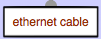
First, create a node class by giving the nodes the same name in each service diagram. Then, to mark the node class as a single physical component instead of two similar “copies”, use its popup menu item “Make single”. Note that the title of single nodes is still shown in red, but that the superscript letter is omitted.
'Make single' can only work when the nodes in the class are in separate services. When the node class has more than one node in a service, the node will flash to indicate that it cannot be converted to a single node.
To revert to a node class, use the popup menu item “Make class” on a single node.
9.8 Notes
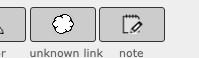
For your convenience notes can be added to a diagram. You add a note by dragging its template onto the workspace, just as you do for diagram nodes.
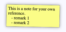
Notes can contain any text. You can resize notes, change their text, duplicate them, delete them, and label and colour them in the same way as for diagram nodes. The text of notes cannot be marked up (bold, font sizes, etc).
9.9 Connecting nodes
Nodes can be connected by dragging the connector (the round decoration at the top of the node) onto another node. If no connection is possible (for example, actors cannot be connected directly to a wireless link), both nodes will flash briefly and no connection will be made. With connections you can:
- connect the node to another node, by dragging from its connector at the top. The connector will enlarge when the mouse pointer hovers over it.
- disconnect two nodes, by clicking its disconnect button. The disconnect button appears in the middle of the connection when you approach it with the mouse.
Connections cannot be moved; they automatically follow the two nodes that they connect.
It is possible to have more connections than allowed by the connection rules for that node type (see Telecommunication service diagrams). This may be useful during editing You will need to remove extra connections later on, for the diagram to be valid. Meanwhile, the node will show a warning triangle.
9.10 Selecting nodes
A set of nodes can be selected, and moved or deleted as a group. Click and drag anywhere on the workspace outside a node to create a selection. While dragging, a blue rectangle indicates the current selection. Move all nodes in the selection by dragging the selection rectangle itself.
Call up the selection menu using the menu indicator in the top-right corner, or by clicking the right mouse button. Use the menu to delete all nodes in the seledction, or to label them collectively.
9.11 The node menu
The popup menu allows several operations to act on a node:
call up the vulnerability assessment window.
label the node, using one of the 8 available labels.
change the icon of the node, depending on the current icon set.
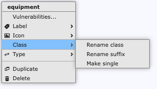
For nodes that belong to a node class:
- change the name of all nodes in the node class. Renaming a single member will make that node fall out of the node class. Use this menu item to rename all member nodes collectively.
- change the suffix from the default of a single letter ('a', 'b', 'c', …) to something more meaningful, such as an abbreviation of the location of the component.
- change the type of the node class from a single identical node into a collection of similar nodes, and vice versa (see Identical nodes).
change the type of the node (e.g. from a wireless link into a cloud).
duplicate the node. This will create a node class.
delete the node.
Changing the node type can be used to correct a mistake, for example to convert an equipment item into a cloud, if you notice during your analysis that the situation is more complex than you previously thought. Note that the vulnerability assessments will not be preserved when changing the node type. Typically, it is not possible to preserve vulnerability assessments, as nodes of different types tend to have very different default vulnerabilities.
Changing the type to something different and back again is a quick way to reset all vulnerability assessments for that node.
9.12 Node labels
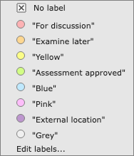
You can use labels to organise nodes. For example, you can label nodes to mark them as 'under review' or to record additional information that is not normally part of the diagrams, such as ownership, responsibility or physical location. Each label is visually indicated in the diagrams using a colour (to disable this, use the setting in the Settings toolbar. Note that these colours have no relation with the colours that are associated with vulnerability levels.
To assign a label, choose one from the Label submenu. To remove the label, choose “No label” from that menu. A node cannot have more than one label.
Labelling nodes is also very useful when clustering nodes in common cause failures view (see Create clusters).
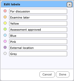
The labels themselves are pre-set to the names of their colour, but can be changed by choosing “Edit labels…” from the node menu, or using the Label button on the Home toolbar. Reset a label to its default value by making it blank.
9.13 Vulnerability assessment window
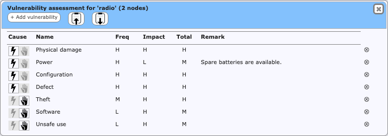
The vulnerability assessment window is called up using the node menu on diagram nodes (except actors). In the vulnerability assessment window, you can add, remove, and assess vulnerabilities to the node. In this window you can:
- rename a vulnerability, by clicking its title (press Enter/click elsewhere to confirm, press Escape to cancel).The name change will apply to all other nodes and (if applicable) to the checklist as well.
- modify the type between natural and malicious using the icons on the left.
- add or edit remarks. Remarks are very useful to explain why this particular assessment was chosen.
- reorder vulnerabilities, by dragging them into the desired order.
- change frequency and impact. Click to activate the selection widget. Click the widget to open it, or type the letter of your choice.
- remove a vulnerability, by clicking the minus-button on the right. See the warning in Adding and removing vulnerabilities about removing vulnerabilities.
Using the buttons in the toolbar, you can:
- add a new vulnerability, by clicking the “+ Add vulnerability” button.
- copy all vulnerabilities onto a clipboard, using the Copy button.
- paste a previously copied set of vulnerability assessments, using the Paste button.
Be careful when pasting vulnerability assessments; these three rules are used:
- Vulnerabilities that were present (based on their name) in the source as well as the destination will be combined.
- On combination, if the probability or impact has been set in both the source and destination, the worst value will be used.
- Any vulnerabilities listed in the source but not yet present in the destination will be created.
It is not yet possible to add/edit descriptions for vulnerabilities, other than using the checklists.