2 The Raster method
General outline of the Raster method and telecom service diagrams.
When using the Raster method, you and the rest of your team will perform a number of tasks. The method will guide you through these tasks in a methodical way, and the Raster tool will assist you in recording your progress. Based on your collective knowledge and expert judgement you will make estimates about the likelihood and impact of various vulnerabilities affecting the telecom services. Based on this analysis, you and your team will draft suitable risk treatment recommendations. The result of your efforts is a report that can be used by a decision maker to take informed business decisions about accepting, reducing, or avoiding the risks.
Raster consists of four stages, shown in the figure below.
- Initiation and preparation
- Single failures analysis
- Common cause failures analysis
- Evaluation
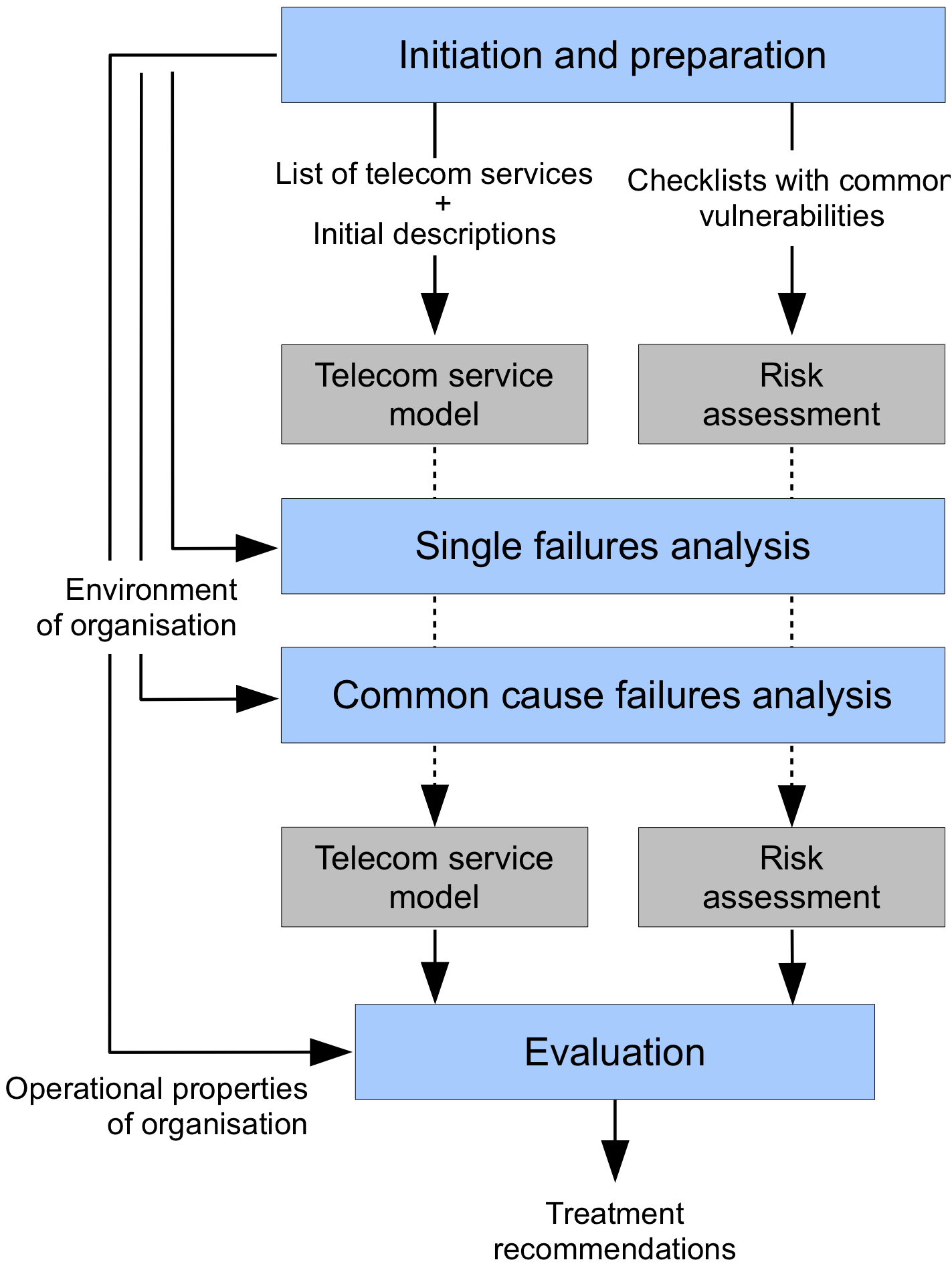
The Initiation and Preparation stage describes the scope and purpose of the assessment. Which telecom services are involved, which users can be identified, who are external stakeholders, and what are the characteristics of the environment in which these services are used?
The Single Failures Analysis stage creates a telecom service diagram for each telecom service in use. These diagrams describe the most relevant telecommunication components, including cables, wireless links, and equipment items. These components are potentially vulnerable. The diagram does not have to be complete in all details. Parts of networks that are less relevant can be captured using a single “cloud” (unknown link). For all components an assessment of all applicable vulnerabilities is done. Only independent, single failures are taken into account during this stage.
The Common Cause Failures Analysis stage takes closer look at failure causes that lead to the failure of multiple components at once. One example is that of independent telecom services that both have a cable in the same underground duct. A single trenching incident may cut both cables at the same time, causing both services to fail. Another example is a large-scale power outage, causing equipment over a large area to fail simultaneously.
The Risk Evaluation stage contains the risk evaluation and creation of the final report. The overall risk level is assessed, and recommendations are done for risk treatment. These recommendations take into account the possible reactions of external stakeholders. The recommendations and their supporting argumentation form the final output of the Raster method. Stage 1, Stage 2, Stage 3 and Stage 4 describe each stage in detail.
2.1 Telecommunication service diagrams
Diagrams are central to the Raster method. A telecom service diagram describes the physical connectivity between components of a telecom service. Diagrams consist of nodes that are connected by lines. Each line represents a direct physical relation. It indicates that the nodes are attached to each other. There cannot be more than one line between two nodes; nodes are either connected or they are not.
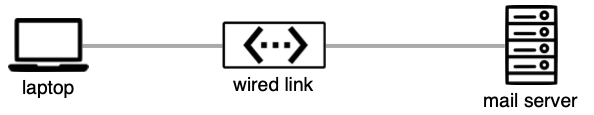
Lines are not the same as cables. When two equipment items are connected via a cable, three nodes are used as in the picture above. The line between equipment and cable shows a physical connection: the cable is plugged into the equipment. There are five types of nodes, each identified by its unique shape.
Different pictures can be used to represent nodes, depending on the icon set used by the Raster tool. The examples below use the Default icon set.
2.1.1 Actors

Actors represent the (direct) users of telecom services. An actor can represent a single individual, or a group of individuals having the same role, e.g. 'journalists' or 'citizens'. Maintenance personnel are not modelled as actors, as they do not participate in communication.

An actor can only be connected to components of type 'equipment' or 'unknown link'. Actors cannot be connected directly to wired or wireless links, and the Raster tool will not allow such connections.
There must be at least two actors in the diagram. There must at least be a person communicating, and one other person to communicate with.
2.1.2 Wired links

Wired links represent passive, physical cables, including their connectors, fittings and joints but excluding any active components such as amplifiers or switches. Fiber optic cables, coaxial cables, and traditional telephony copper pairs are typical examples of wired links. The two equipment items connected by the link are not part of the wired link itself, and need to be included in the model separately, either as equipment items or unknown links.
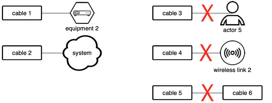
Each wired link has exactly two connections, each to a component of type either 'equipment' or 'unknown link'. To connect a wired link to an actor, wireless link, or an other wired link, place an equipment node in between.
Each wired link has some fixed capacity, a physical location (including a height above or below ground level). These properties need to be known in sufficient detail.
2.1.3 Wireless links

Wireless links represent direct radio connections, excluding any intermediate components. The transmission and reception installations are not part of the wireless link, and have to be modelled separately as equipment items. A wireless link can connect two or more nodes.
Each wireless link has a fixed capacity, but unlike wired links a wireless link does not always have a fixed location. Transmitters and receivers can be mobile or nomadic. The coverage area depends on factors such as transmission power and antenna properties. Wireless links have a fixed frequency or band. All of these properties need to be described in sufficient detail.
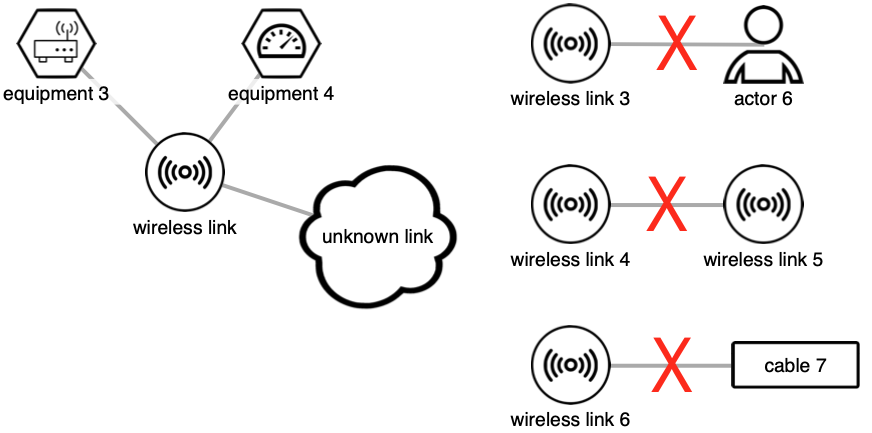
Each wireless link has at least two connections, each to a component of type either 'equipment' or 'unknown link'. It can have more than one, as in the example above. To connect a wireless link to an actor, equipment, or an other wireless link, place an equipment node in between.
2.1.4 Unknown links

Unknown links (cloud shapes) represent parts of networks for which insufficient information is available, or that do not need to be described in detail. Unlike wired and wireless links, that represent a single communication channel, unknown links are composed of equipment and wired and wireless links.
Because unknown links are collections of equipment and wired and wireless links, they can be used in any place where these nodes can be used. In short, unknown links can connect to any other node type. Also, unknown links can be connected to any number of nodes.
2.1.5 Equipment
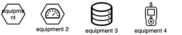
Equipment nodes represent all other physical components of telecom networks, such as switches, exchanges, routers, amplifiers, radio transmitters, radio receivers etc. An equipment node may model a single piece of equipment or an entire installation.
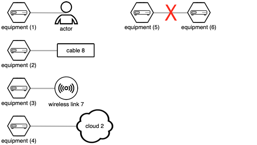
Each equipment node must be connected with at least one other component. An equipment node cannot be connected directly to another node of type 'equipment'.
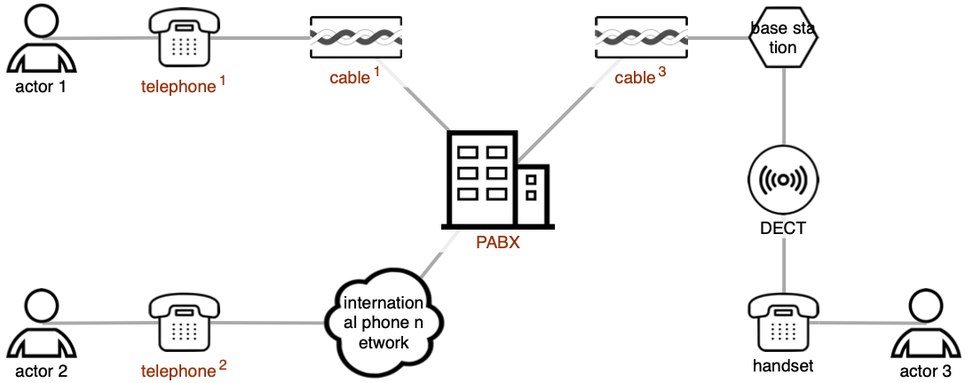
2.1.6 Example
The figure below shows an example of a valid telecom service diagram. The diagram shows three actors, communicating via telephony. Two actors are connected to the same private exchange (PABX); the third actor is abroad. One actor uses a wireless DECT handset and base station, the others use fixed handsets. We have no knowledge (yet) of the other portions of the network, other than that some PABX must exist, and some kind of international telephony network to facilitate the calls.